1. Product Introductions
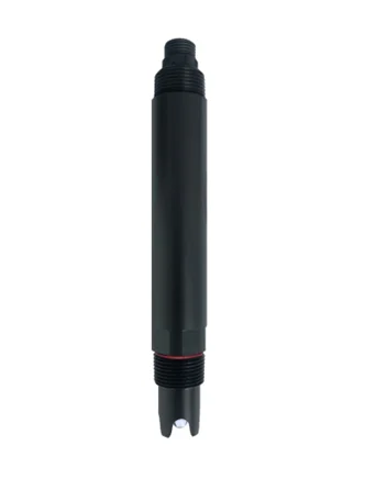
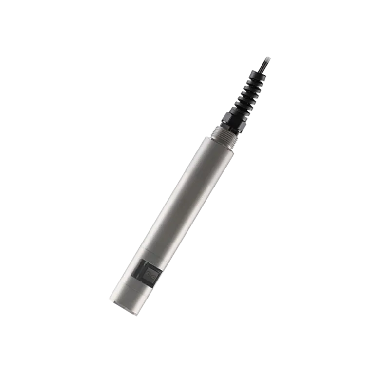
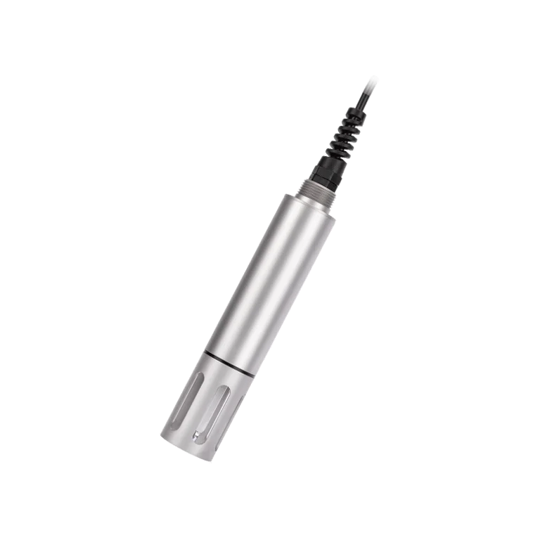
The Ammonia Nitrogen Sensor is a high-precision digital water quality monitoring device featuring an RS485 communication interface and standard Modbus protocol for easy system integration.
Built with a corrosion-resistant housing and rated IP68, it operates reliably in harsh industrial and environmental conditions such as wastewater treatment, surface water monitoring, and aquaculture systems.
The sensor employs industrial-grade ion-selective electrodes (ISE) that ensure long-term stability and high accuracy. It requires no chemical reagents, produces no secondary pollution, and demands minimal maintenance, resulting in low operational costs and high efficiency.
Additionally, it is equipped with a built-in PT1000 temperature sensor and an automatic temperature compensation algorithm, delivering an exceptional measurement accuracy of ±0.1°C under varying environmental conditions.
2. Operation Principle
The Ammonia Nitrogen Sensor determines ammonia concentration based on the ion-selective electrode (ISE) principle.
When the sensing membrane of the electrode comes into contact with the water sample, ammonium ions (NH₄⁺) selectively interact with the electrode’s sensitive membrane, generating a potential difference.
This potential is then converted into an electrical signal according to the Nernst equation, which reflects the logarithmic relationship between ion activity and electrode potential.
Through signal conditioning and digital processing, the system outputs accurate and stable ammonia nitrogen concentration readings.
3. Electrical Connection
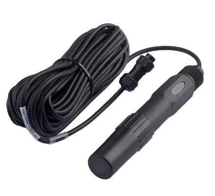
The cable is a 4-core twisted-pair shielded wire with the following pinout:
Red wire: Power supply (12–24 VDC)
Black wire: Ground (GND)
Blue wire: 485A
White wire: 485B
Before powering the sensor, always verify the wiring sequence to prevent potential damage caused by incorrect connections.
As the cable may be submerged in water (including seawater) or exposed to air for extended periods, it must be corrosion-resistant. All connection points should be properly waterproof-sealed to ensure long-term operational reliability.
4. Maintenance and Servicing
Before testing, the electrode should be soaked in activation solution for 24 hours to complete activation, then thoroughly rinsed with deionized water. If the electrode is not in use for an extended period (over two weeks), it must be stored dry, and the sensing component should be covered with a protective cap
Check whether the terminals are dry. If contaminated, clean them with anhydrous alcohol and dry thoroughly before use. Avoid prolonged immersion in distilled water or protein solutions, and prevent contact with silicone-based oils. For electrodes with extended use, if the PVC membrane becomes translucent or accumulates deposits, rinse with distilled water (or deionized water). If measurement errors occur due to prolonged electrode usage, perform calibration.
If calibration and measurement remain impossible after performing the above maintenance and care procedures, this indicates that the electrode has failed and should be replaced
Primary interfering ions are listed in the table below:
The concentration of interfering ions that induces a 10% error under varying ammonium ion concentrations
|
Interferences (moles/liter)
|
10-4 M Ammonium
|
10-3 M Ammonium
|
10-2 M Ammonium
|
|
H+
|
< 2
|
< 1
|
< 1
|
|
Li+
|
0.2
|
0.5
|
0.5
|
|
Na+
|
0.005
|
0.08
|
0.8
|
|
K+
|
7*10-5
|
6*10-4
|
6*10-3
|
|
Cs+
|
0.003
|
0.05
|
0.5
|
|
Mg3+
|
> 0.5
|
> 1
|
> 1
|
|
Ca2+
|
> 0.2
|
> 1
|
> 1
|
|
Sr2+
|
> 0.2
|
> 1
|
> 1
|
|
Ba2+
|
> 0.1
|
> 0.5
|
> 0.5
|
|
Zn2+
|
0.001
|
0.01
|
0.1
|
|
N2H5+
|
> 0.1
|
> 0.1
|
>0.1
|
|
Bu4N+
|
1*10-5
|
1*10-4
|
1*10-3
|
5. Sensor Calibration
Zero Point Calibration
1. Immerse the sensor in a zero-point standard solution.
2. Wait approximately 5 minutes until the reading stabilizes.
3. Confirm that the value falls within the allowable error margin.
4. If deviation occurs, perform zero-point calibration (refer to the calibration appendix).
Slope Calibration
1. Immerse the sensor in a slope standard solution.
2. Wait 5 minutes for stabilization, then verify the reading accuracy.
3. If deviation is detected, carry out slope calibration following standard procedures.
1. Operating on the scattered light principle with a built-in temperature sensor;
2. Supports RS-485 and Modbus/RTU protocols;
3. Optical fiber structure with strong resistance to external light interference;
4. Infrared LED light source for high stability;
5. IP68 waterproof rating, submersible up to 20 meters depth;