EC Sensor
Model No.: EC Sensor
Communication method: RS485(Modbus RTU)
Measurement range: 0~20 mS/cm(0~99 ℃)
Measurement precision: ±0.5%
Measurement principle: Graphite electrode methodVoltage: DC12V ~ DC24V
Protection class: IP68
Model No.: EC Sensor
Communication method: RS485(Modbus RTU)
Measurement range: 0~20 mS/cm(0~99 ℃)
Measurement precision: ±0.5%
Measurement principle: Graphite electrode methodVoltage: DC12V ~ DC24V
Protection class: IP68
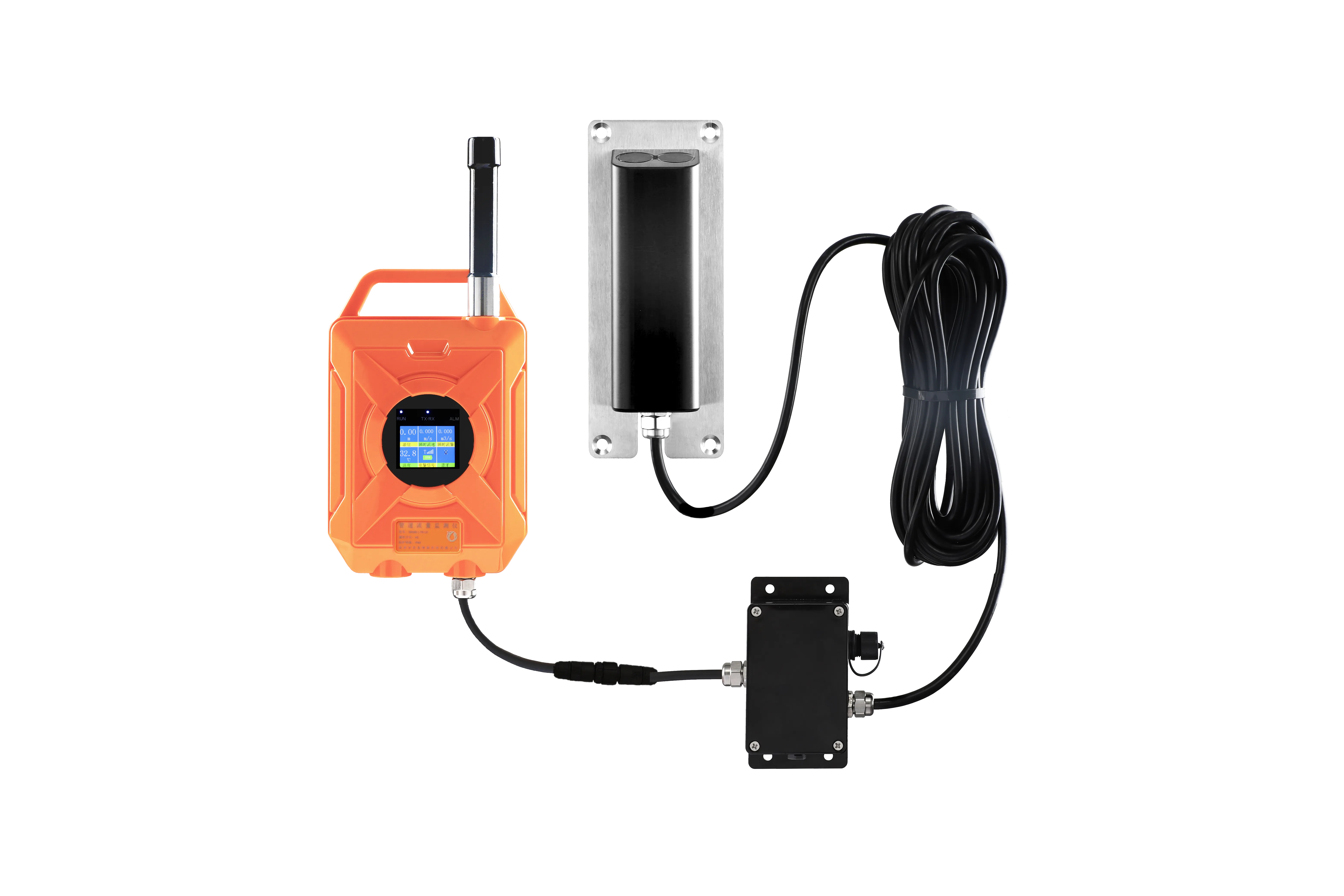
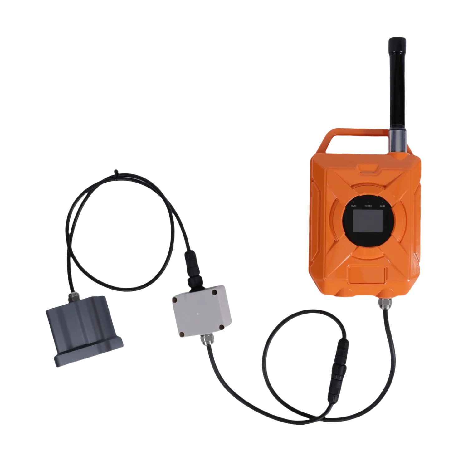
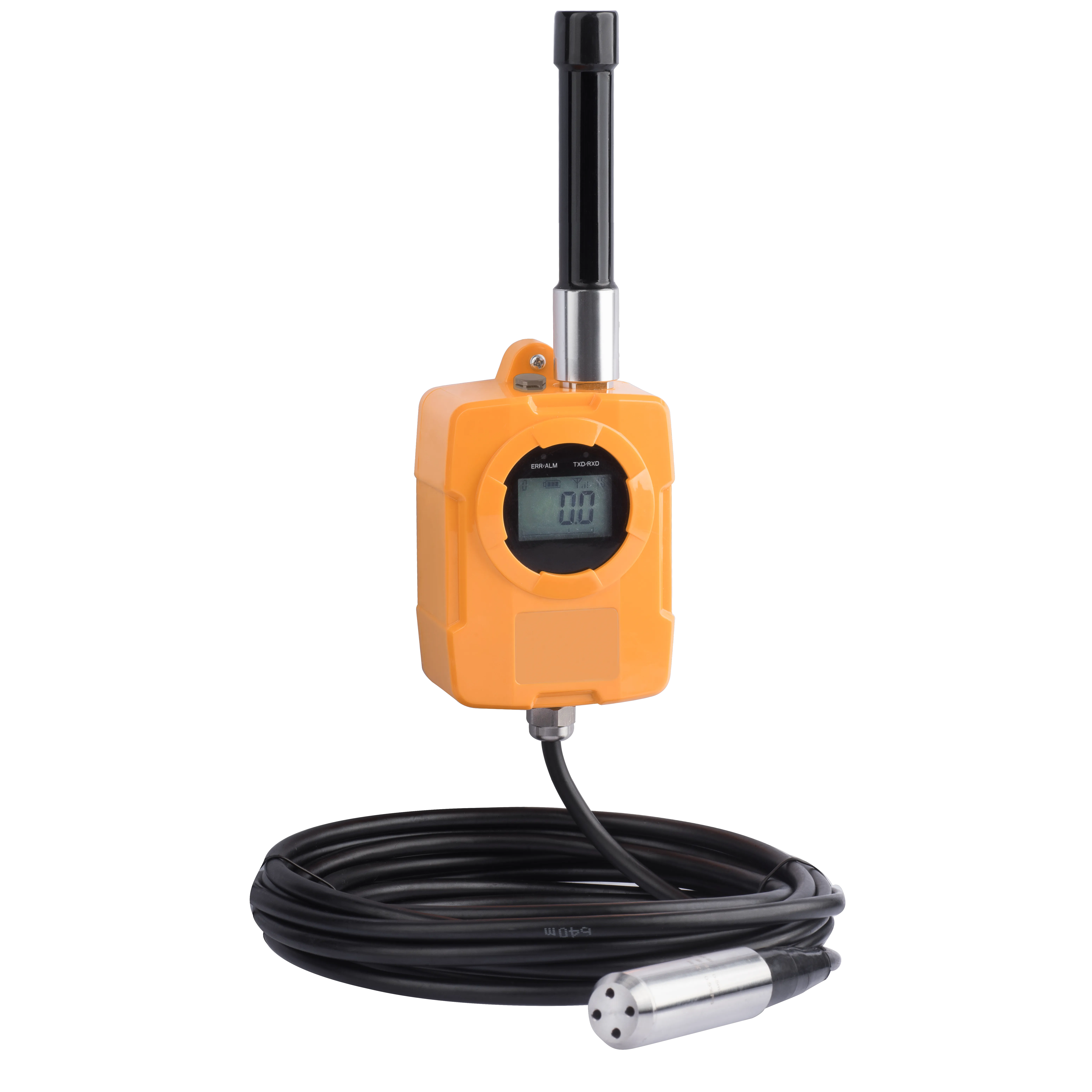
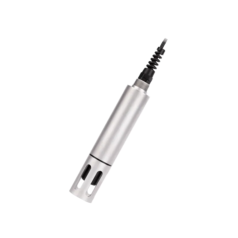
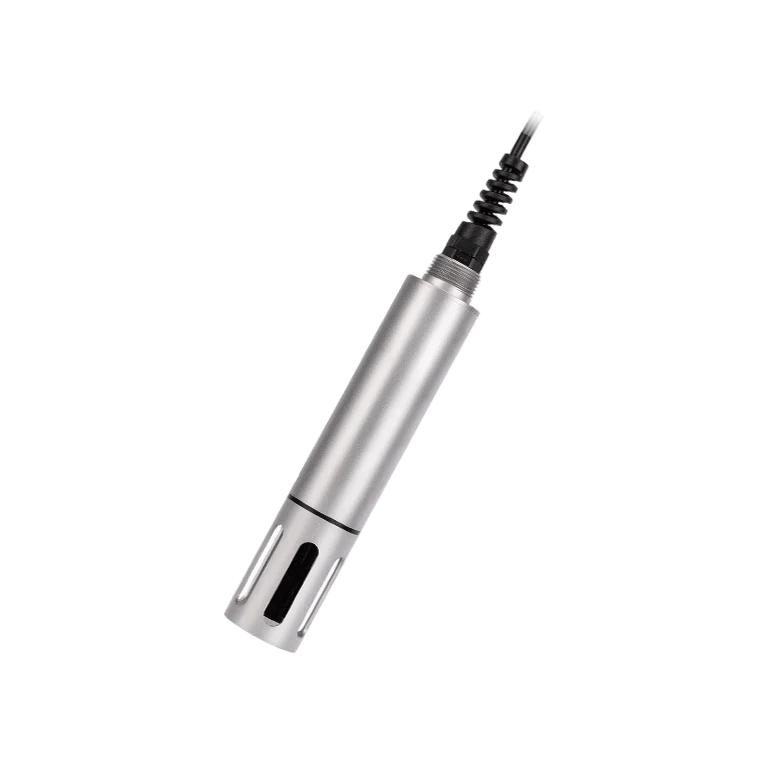
The EC Sensor is a digital sensor featuring an easy-to-integrate RS485 communication interface and standard Modbus protocol, It is equipped with a corrosion-resistant housing, IP68 protection rating, suitable for operation in various harsh working environments; Using an industrial-grade graphite quadrupole electrode, suitable for full-scale conductivity measurements; The electrode constant remains highly stable, unaffected by polarization effects; automatic compensation for surface contact resistance ensures immunity to contamination; Equipped with a built-in PT1000 temperature sensor and compensation algorithm, achieving an accuracy of ±0.1℃;
By leveraging the relationship between salinity, TDS, and conductivity, the system can extend to measure salinity parameters, broadening its application scope; the integrated liquid level measurement feature, ensure widespread application in urban pipeline monitoring.
Conductivity is a measure of a medium's ability to conduct electrical current. unit by μS/cm or mS/cm. At room temperature, pure water has a conductivity of less than 0.05 μS/cm, natural or surface water ranges between 100–1000 μS/cm, while acidic or alkaline solutions can exhibit conductivity exceeding 1000 mS/cm.
The conductivity of a solution is determined by measuring the voltage and the current between two coaxial electrodes immersed in the solution . Based on Ohm's Law, the solution's resistance is calculated as R=V/I, and the reciprocal of this resistance defines the conductance S=1/R. By incorporating the electrode-specific constant K, the conductivity of the solution can be directly derived
The cable is a 4-core twisted-pair shielded wire with the following pinout:
Red wire: Power supply (12–24 VDC)
Black wire: Ground (GND)
Blue wire: 485A
White wire: 485B
Before energizing the device, thoroughly verify the wiring sequence to prevent damage resulting from incorrect connections.
Given that the cables may be submerged in water (including seawater) or exposed to air for extended periods, they must possess corrosion-resistant properties. Additionally, all connection points must undergo waterproof sealing to ensure long-term reliability.
Regular electrodes require periodic cleaning and calibration, with maintenance intervals determined by the client based on their specific operating conditions.
Standard electrode cleaning procedure:
Remove deposits using a soft-bristled brush (avoid scratching the electrode surface), rinse with distilled water, then perform calibration
Inductive electrode cleaning procedure:
Inductive electrodes are generally maintenance-free. Contamination or minor scaling on the housing will not affect their normal operation;
If cleaning is required, remove deposits using a soft-bristled brush or sandpaper, rinse with distilled water, then perform calibration procedures;
Due to the fact that inductive electrodes often operate in environments prone to scaling or dirt, the cleaning force can be appropriately increased. Slight scratches on the surface of the electrode do not affect its normal operation, but it is important to avoid penetrating the outer shell of the electrode;
a)Zero-point calibration
Rinse the sensor with distilled water and blot dry using filter paper. Connect the sensor to power, vertically position it in air, allow it to remain stationary for approximately 3 minutes. Once the readings stabilize, proceed with zero-point calibration.
b)Slope calibration
Position the sensor vertically in the standard solution (10% to full scale range). Ensure the sensor is at least 2 cm away from the container's bottom and sidewalls. Proceed with slope calibration after stabilization.
1. Drinking water/surface water/various water supply/industrial water treatment;
2. Signal output: RS-485(Modbus/RTU protocol) is convenient to connect to third-party equipment such as PLC, DCS, industrial control computer, general controller, paperless recording instrument or touch screen;
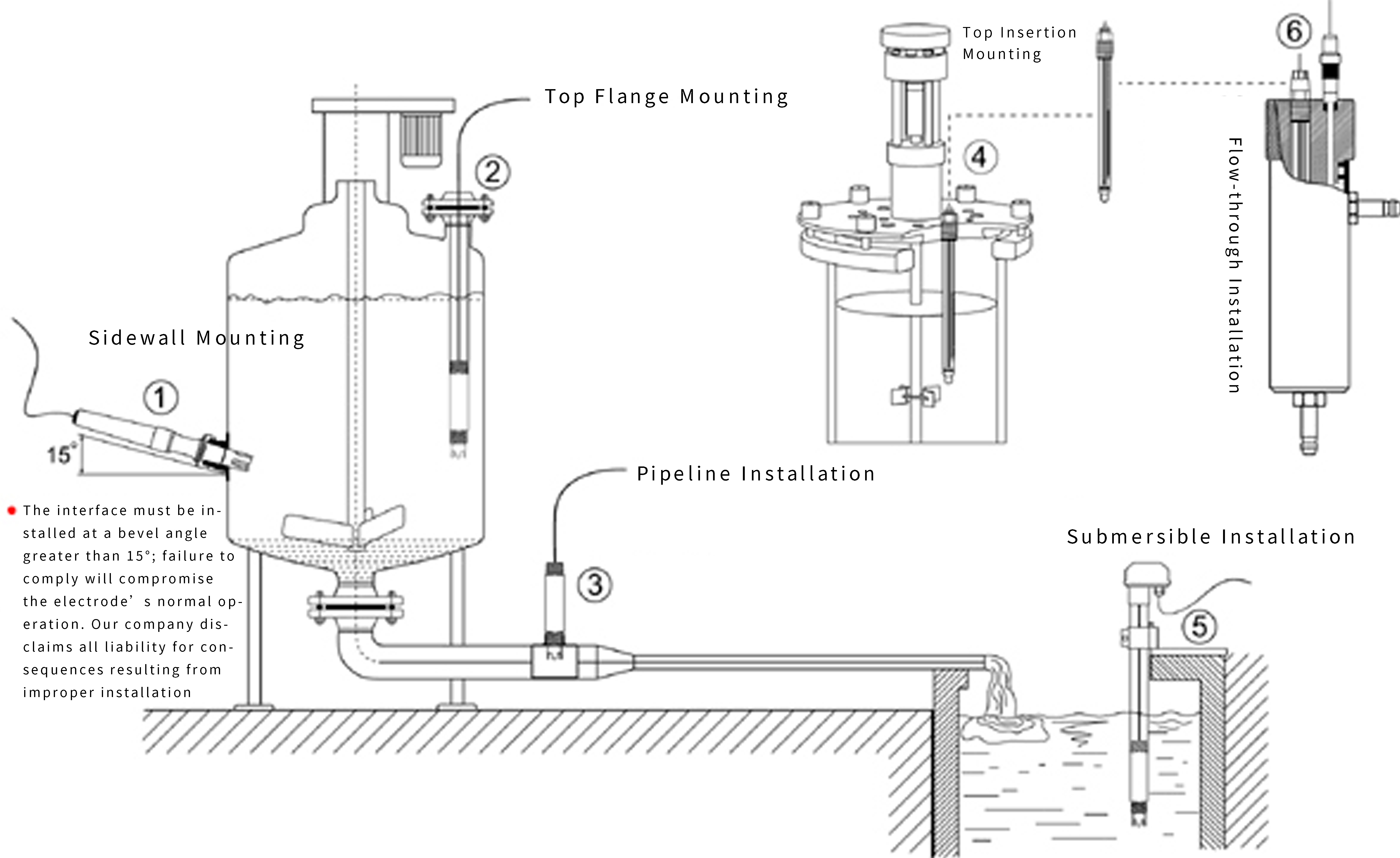
3. Immersion installation, with 3/4NPT pipe thread, easy to sink installation or installation in pipes and tanks;
4. IP68 protection level;
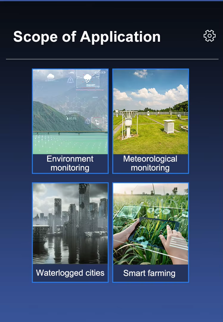
Focusing on the application of intelligent sensing technology in drainage pipe networks and river level monitoring, we are a professional provider of overall solutions for online water monitoring. Our main products include wireless liquid level monitoring devices, wireless pressure sensors, online water quality analyzers, float type water quality monitoring stations, rainwater monitoring stations, river flow monitoring stations, etc. Our products are widely used in smart cities, environmental protection, municipal engineering, chemical industry, power, sewage treatment, emergency rescue and other fields.
4th Floor, Building A, Xifengcheng Industrial Park, Fuyuan 2nd Road, Zhancheng Community, Fuhai Street, Bao'an District, Shenzhen City, Guangdong Province, China
Copyright © 2015-2025 ShenZhen StarWSN Science & Technology Co.,Ltd All Rights Reserved