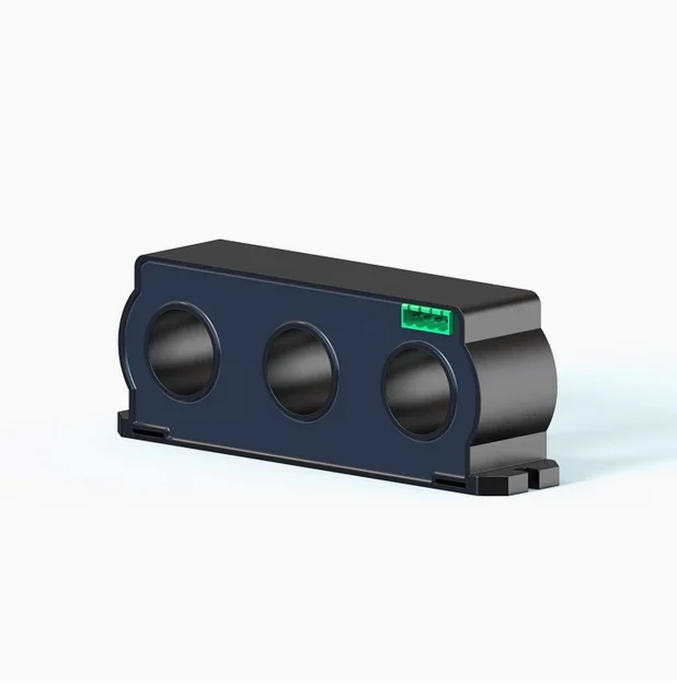
Current Transformer
Model NO.: Current transformer
Operating frequency: 50400Hz
Rated output: 10mA5A
Measuring range: 10 In130In
Working temperature: -25°-75°
Model NO.: Current transformer
Operating frequency: 50400Hz
Rated output: 10mA5A
Measuring range: 10 In130In
Working temperature: -25°-75°
1. Introduction
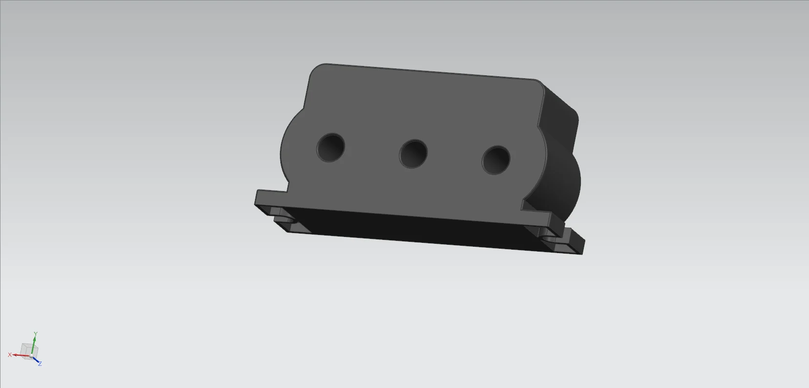
The Current Transformer (CT) is an essential electrical measurement and protection device based on the principle of electromagnetic induction. It is designed to convert high primary currents in three-phase circuits into proportionally smaller secondary currents, providing safe and standardized current signals for measuring instruments, protective relays, and monitoring systems.
As a vital component of smart grids and industrial power systems, the current transformer ensures accurate current measurement, reliable system protection, and efficient power management. It is widely used in power generation, transmission, distribution, and energy metering—safeguarding both personnel and equipment while supporting the stable operation of electrical networks.
2. Principle
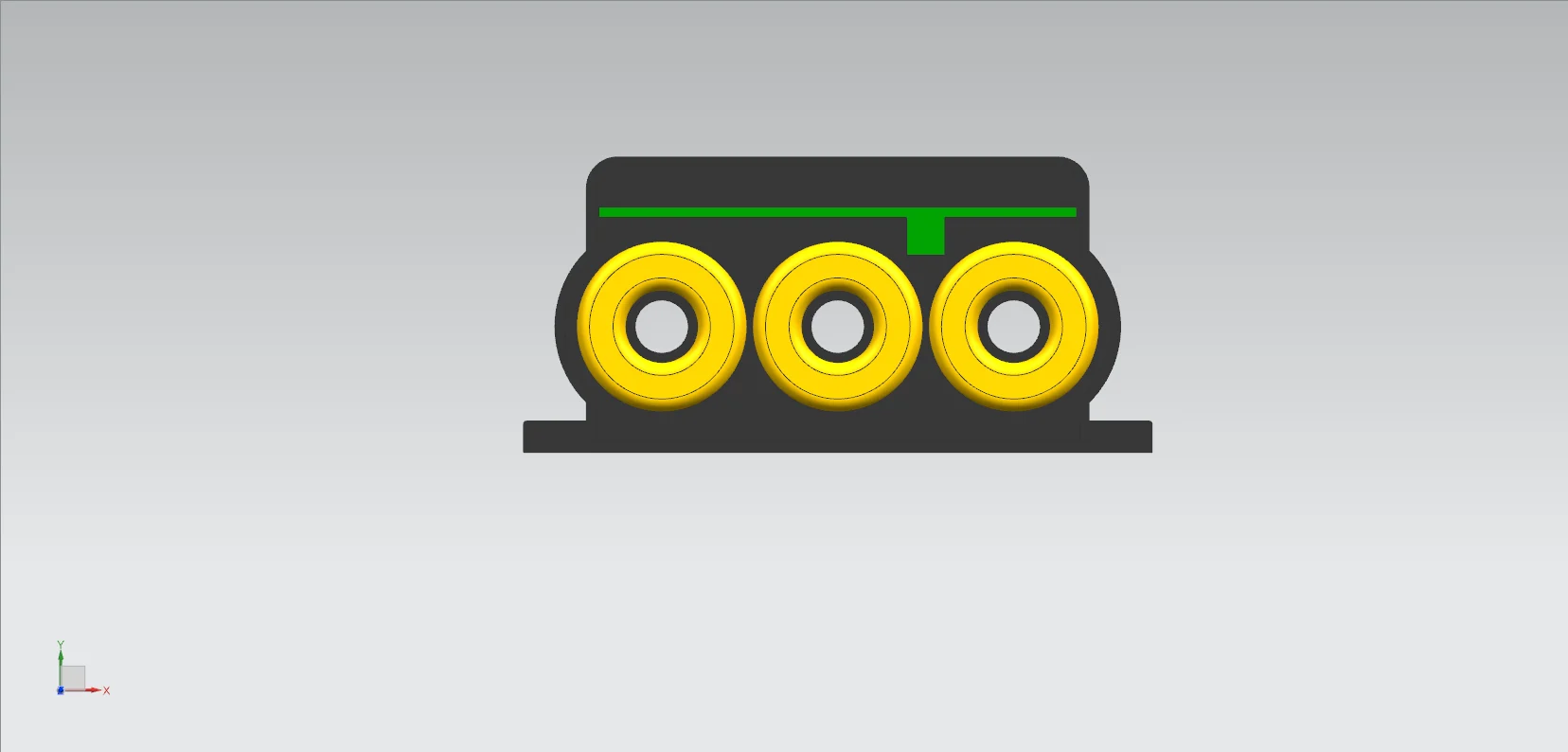
When a three-phase alternating current flows through the primary winding of a current transformer (CT), it generates an alternating magnetic flux in the iron core. This flux passes through the secondary winding, according to the law of electromagnetic induction, induces a proportional secondary current in the secondary winding relative to the primary current. The ratio of the magnitude of the secondary current to that of the primary current equals the inverse of the ratio of the number of turns in the primary winding to those in the secondary winding. This principle enables the conversion of large primary currents to smaller secondary currents.
3. Function
3.1 Current measurement
• Safe Measurement for High/Low Voltage Circuits
Direct measurement of high currents is hazardous and impractical. A three-phase current transformer proportionally converts large primary currents to small, standardized secondary currents, allowing safe, precise readings.
For example, in a 10 kV distribution system, a CT converts a 1000 A current to 5 A, enabling standard ammeters to display the current accurately.
• Multi-Device Compatibility
CTs seamlessly interface with various instruments such as ammeters, power meters, and energy analyzers, providing standardized current signals for measuring power, current, and energy consumption. In industrial power rooms, CTs serve as the foundation for accurate metering and billing.
3.2 Protective relaying
• Fault Current Detection
During short circuits or overloads, current levels spike dramatically. The CT immediately senses these fault currents and transmits them to protective relays, which then trip the circuit to isolate the fault and prevent equipment damage.
• Precision Protection Coordination
CTs supply accurate current data for overcurrent, overload, and differential protection schemes. Their precision ensures protective devices respond appropriately to fault types and severities, enhancing overall system reliability.
3.3 System Monitoring and Automation
• Accurate Billing and Energy Management
The CT is integral to electrical energy metering systems. By providing a proportional secondary current, it enables energy meters to accurately measure consumption, ensuring fair billing across industrial, commercial, and residential users.
• Multi-Type Metering CompatibilityActive and Reactive Power Monitoring
CTs provide accurate current data for both active and reactive energy metering, supporting advanced analytics on power quality, load balance, and power factor optimization.
3.4 System monitoring and control
• Real-Time System Status Assessment
Monitoring secondary currents from CTs provides insights into phase balance, load distribution, and fault conditions. Any detected imbalance helps operators perform preventive maintenance and improve grid stability.
• Foundation of Smart Grid Control
In automated power systems, CTs deliver key current signals that enable automatic load adjustment, reactive compensation, and self-regulating control—core elements of smart grid infrastructure.
4. Installation and Maintenance Guidelines
4.1 Pre-Installation Inspection
• Check for mechanical damage or deformation, ensuring nameplate parameters match design specifications.
• Measure the insulation resistance of the secondary winding; if resistance is abnormally low, perform drying treatment or replace damaged insulation before installation.
4.2 Installation steps
• Choose the proper installation method—such as bracket or busbar mounting—based on site requirements.
• Ensure firm, vibration-free installation to prevent mechanical stress on windings.
• Connect the primary winding in series with the main circuit and the secondary winding to measuring instruments and relays according to correct polarity and wiring diagrams.
4.3 Precautions for Use
• Never open the secondary circuit while the primary is energized. Open-circuit conditions can induce dangerously high voltages that threaten personnel and equipment.
• Keep the secondary load within rated capacity to avoid measurement errors or overheating.
• Perform regular inspections for abnormal heat, noise, or odor. In case of irregularities, immediately de-energize the system and inspect for faults.
|
Item name |
Parameter |
|
Electrical parameters |
|
|
Operating frequency |
50400Hz |
|
10mA5A |
|
|
Measurement range |
10In130In |
|
Rated output |
01v(A or)00.25mA |
|
Ratio error |
±0.1 |
|
Phase error |
±10分 |
|
Dielectric strength |
2.5KV/1mA/1min |
|
Insulation resistance |
DC500V/1000MΩ /min |
|
Mechanical parameters |
|
|
Housing |
ABS,Flame retardant grade 94-V0 |
|
Bobbin |
PBT |
|
Core |
Nickel Steel or Nanocrystalline |
|
Internal structure |
Environmentally Friendly Epoxy Resin Casting |
|
Installation procedure |
Screw fixation |
|
Working temperature |
-25 +75 |
|
Ambient humidity |
85 |
|
Wiring Configuration |
Terminal Type/Shielded Stranded Wire 1.5m |

Focusing on the application of intelligent sensing technology in drainage pipe networks and river level monitoring, we are a professional provider of overall solutions for online water monitoring. Our main products include wireless liquid level monitoring devices, wireless pressure sensors, online water quality analyzers, float type water quality monitoring stations, rainwater monitoring stations, river flow monitoring stations, etc. Our products are widely used in smart cities, environmental protection, municipal engineering, chemical industry, power, sewage treatment, emergency rescue and other fields.
4th Floor, Building A, Xifengcheng Industrial Park, Fuyuan 2nd Road, Zhancheng Community, Fuhai Street, Bao'an District, Shenzhen City, Guangdong Province, China
Copyright © 2015-2025 ShenZhen StarWSN Science & Technology Co.,Ltd All Rights Reserved